A pneumatic valve is a device that controls compressed air in a pneumatic system. It starts, stops, directs, or regulates the air that drives cylinders, grippers, and other actuators. Most pneumatic valves fall into three functional groups: directional control valves, which decide where air goes; flow control valves, which set how fast it moves; and pressure control valves, which set how hard it pushes. A valve can be operated by hand, by a mechanical contact, by pilot air, or by an electric solenoid.
What Is a Pneumatic Valve?
A pneumatic valve is the control element between your compressed air supply and the equipment that does the work. On its own, compressed air is just stored energy. The valve decides when that energy reaches an actuator, which path it takes, and at what speed or pressure.
A few terms are worth defining up front:
- Port: a connection on the valve body, such as supply, outlet, or exhaust.
- Position: a switching state the valve can hold, such as open or closed.
- Actuator (of the valve): the mechanism that shifts the valve, such as a lever, a pilot signal, or a solenoid.
- Normally closed (NC): blocks airflow when the valve is not actuated.
- Normally open (NO): passes air when the valve is not actuated.
Pneumatic valves sit at the heart of every circuit, which is why the pneumatic valves category is one of the largest in industrial automation.
How Do Pneumatic Valves Work?
Pneumatic valves work by shifting an internal element, usually a spool or a poppet, to change which ports are connected inside the valve body. When the element moves, it opens one air path and closes another. That change sends air to an actuator or vents it to exhaust.
What Is the Pneumatic Valve Working Principle?
The working principle follows the same basic sequence in most designs:
- At rest: the valve holds its default position, typically set by a spring or by air pressure.
- Actuation: a signal arrives from a lever, a roller, a pilot air line, or an energized solenoid.
- Shift: the spool or poppet moves and reconnects the ports.
- Air flows: supply air reaches the actuator, and air from the other side vents through the exhaust port.
- Return: when the signal is removed, the valve either returns to rest or stays where it is.
That last step matters. A monostable valve returns to its rest position by spring or air force once the signal is removed. A bistable valve stays in position after a short signal and needs a separate signal to switch back. Double pilot and double solenoid valves are common bistable designs.
Spool vs. Poppet: What Is the Difference?
A spool valve uses a sliding cylindrical spool with lands and grooves to connect ports. A poppet valve uses a disc or cone that lifts off a seat to open a path. Both designs are widely used, and ISA notes that a solenoid typically shifts either a spool or a poppet in common directional valves.
What Are the Main Types of Pneumatic Valves?
The main types of pneumatic valves are grouped by function: directional control, flow control, pressure control, and non-return or logic valves. The table covers the types you will find most often in industrial automation.
| Valve Type | What It Does | Typical Use |
|---|---|---|
| 2/2 directional valve | Opens or closes a single air path | Simple on/off switching, isolating part of a system |
| 3/2 directional valve | Pressurizes and exhausts one outlet | Single-acting cylinders, piloting another valve |
| 5/2 directional valve | Alternates air between two outlets | Double-acting cylinders, rotary actuators |
| 5/3 directional valve | Adds a center position | Stopping, holding, or letting an actuator float mid-stroke |
| Flow control valve | Restricts airflow to set speed | Cylinder speed adjustment |
| Pressure regulator | Reduces and holds downstream pressure | Setting working pressure for a machine or actuator |
| Check valve | Allows flow in one direction only | Preventing backflow |
| Shuttle valve | Passes air from either of two inlets to one outlet | Controlling one actuator from two signal sources |
| Quick exhaust valve | Vents an actuator directly, close to the cylinder | Faster cylinder return |
| Proportional valve | Varies flow or pressure in response to a variable signal | Precise, adjustable control |
What Are Directional Control Valves?
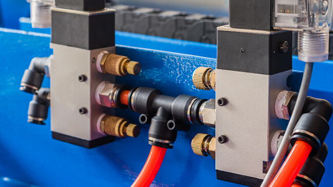
Directional control valves decide which way air flows, and they are the most common pneumatic valve type. They are described by ports and positions. A 3/2 valve has three ports and two positions, so it can pressurize only one chamber, which suits a single-acting cylinder with spring return. A 5/2 valve adds working and exhaust ports so both cylinder chambers can be pressurized and vented. A 5/3 valve adds a middle position, which can be closed, pressurized, or exhausted depending on the design.
For a closer comparison of these configurations, see our guide to 2-way vs. 3-way vs. 5-way pneumatic valves.
What Are Flow and Pressure Control Valves?
Flow control valves set how fast air moves, which sets actuator speed. Speed controllers such as PISCO speed controller push valves are a common example. Pressure control valves set how much pressure reaches the equipment, which sets force. A regulator like the AirTAC GP precision regulator holds a steady working pressure. Regulators are also part of every FRL unit.
How Are Pneumatic Valves Actuated?
Pneumatic valves are actuated in four main ways, and the method decides how the valve fits into your control system:
- Manual: a person operates a button, lever, or foot pedal. Humphrey manual valves are an example.
- Mechanical: a moving part of the machine, such as a cam or roller, shifts the valve.
- Pneumatic (air pilot): a separate pilot air signal shifts the valve. ISA notes that air-operated valves are used for remote operation, and Humphrey air piloted valves work this way.
- Electric (solenoid): an electric coil, usually controlled by a PLC, shifts the valve.
Methods can be combined, such as a solenoid to shift the valve and a spring to return it.
Pneumatic Valve vs. Solenoid Valve: What Is the Difference?
A solenoid valve is a type of pneumatic valve, not an alternative to one. “Pneumatic valve” describes what the valve controls: compressed air. “Solenoid valve” describes how it is actuated: by an electric coil. So a valve can be both, and many modern pneumatic valves are solenoid operated, such as Humphrey solenoid valves and AirTAC solenoid valves.
To learn how the coil and plunger work, read what a solenoid valve is, and for the two main solenoid designs see direct-acting vs. pilot-operated solenoid valves.
What Is a Pneumatic Control Valve?
The term “pneumatic control valve” is used in two ways, so it helps to know which one you mean.
In factory automation, it usually means any valve that controls a pneumatic circuit, such as a directional, flow, or pressure control valve.
In process industries, it usually means a valve on a pipeline that is positioned by a pneumatic actuator to regulate a process fluid. ISA describes these as using actuators and positioners driven by a controller: air on the diaphragm opens the valve, and springs close it when pressure is lost or reduced. For that kind of valve, see the Habonim control valve and our comparison of ball valves vs. control valves.
How Do You Read Pneumatic Valve Symbols?
Pneumatic valve symbols show a valve’s positions, flow paths, and actuation methods in a circuit diagram. The rules for these symbols are set out in ISO 1219-1, the international standard for fluid power graphical symbols.
The basics are simple:
- Each square represents one valve position. Two squares mean a two-position valve.
- Arrows inside a square show flow paths in that position.
- A “T” shape shows a blocked port.
- Symbols on the left and right show how the valve is actuated, such as a solenoid, a spring, a lever, or a pilot line. Each method has its own symbol, and combined methods show two symbols side by side.
Ports are also commonly numbered: 1 for supply, 2 and 4 for working outlets, and 3 and 5 for exhaust. Reading the symbol from the position the valve is drawn in tells you what happens at rest.
How Do You Choose a Pneumatic Valve?
Start with what the actuator needs, then work back to the valve:
- Actuator type: a single-acting cylinder usually needs a 3/2 valve, and a double-acting cylinder usually needs a 5/2 or 5/3 valve.
- Rest behavior: decide whether the valve should be normally closed or normally open, and whether it should be monostable or bistable.
- Actuation: choose manual, mechanical, pilot, or solenoid based on your control system.
- Flow and pressure: size the valve for the airflow your actuator needs and add flow or pressure control where speed or force matters.
- Air quality: clean, dry air from proper air preparation systems helps valves shift reliably.
If you are also choosing the actuator itself, our guide on how to choose a pneumatic actuator covers the other half of the circuit.
What Is a Pneumatic Valve Used For?
A pneumatic valve is used to control motion and force in machines that run on compressed air. Typical jobs include extending and retracting cylinders, opening and closing grippers, switching vacuum on and off, and setting speed or pressure for a process.
You will find them in packaging lines, automotive assembly, electronics production, food processing, and general industrial manufacturing, as well as in process plants where pneumatic actuators position larger valves. Manufacturers such as Humphrey Products build valves for many of these applications.
Frequently Asked Questions
It is a switch for compressed air. It decides when air flows, where it goes, and how fast or how hard it pushes the equipment it feeds.
Directional control valves, flow control valves, and pressure control valves. Check, shuttle, and quick exhaust valves are common additions.
A solenoid valve is a pneumatic valve that is actuated electrically. Pneumatic valves can also be actuated manually, mechanically, or by pilot air.
It means five ports and two positions. A 5/2 valve is commonly used to drive a double-acting cylinder in both directions.
ISO 1219-1 sets out the graphical symbols used for fluid power components and circuit diagrams.
Conclusion
A pneumatic valve controls the compressed air that powers automated equipment. Directional valves decide where air goes, flow control valves set speed, and pressure control valves set force. Understanding ports, positions, actuation, and symbols makes it much easier to read a circuit and choose the right valve.
If you are specifying valves for a new machine or replacing existing ones, get in touch and we can help you match the right valve to your application.